I'm looking for documentation for a CR90 receiver

HA3KGX

Well-Known Member
Hi!

My name is Alexander, I hope it's not a problem to write in English?
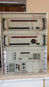
I have a CR90 radio receiver that I'm trying to repair but unfortunately I can't find wiring diagrams anywhere.

Maybe someone isn't here?

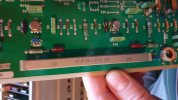
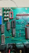
The DC-DC converter card in the device is not good, unfortunately it was not made by someone original. When I fix it, the device turns on, a couple of basic LEDs light up but don't come to life unfortunately. Pressing the buttons changes things on the display but does not respond as it should.

Thanks!
 
Hi Alexander!
English is OK!
The DC/DC supplies three voltages:
+18 V
-18 V
+5,3 V
Check this first!
 
Hi The voltage levels are fine, thanks for writing. I’ve been searching the internet for days for documentation but can’t find anything unfortunately. The radio turns on, but only a few LEDs light up, when I press the ON button when it is on, the mode, bandwidth, etc. appear randomly for a moment ... But it also disappears, there is only one number ...
 
This is what it looks like, there is a battery at the end of the cord temporarily
 

Attachments

  • 20220408_160810.jpg
    20220408_160810.jpg
    1,1 MB · Views: 45
Hi, you can possibly ask here as he have made some replacement Synthcard for the CR90 he will most likely have access to the full schematic


73
 
Hi!

Looks like the machine is starting to come to life, I can already type in a frequency. I can also specify bandwidth.
The reed relay on button B was broken and kept short-circuited, eliminating the above.
However, the number two pushbuttons are not good yet, nor is an LED display, the two are also important because the code of the modes starts with a double, for example B23, etc.
That's how it goes but I can only hear a soft pop, I think it's because I can't type a mode for him.
I ordered a part and then I will upload pictures if anyone is interested in the end result!

Thanks

(I'm sorry for the errors, I use a compiler)
 
Hi!

Today the part arrived, led driver ic, the machine started for the first time, it sounds beautiful!
All its functions work except LSB, does anyone have an idea where to look for the bug?
I replaced the reed relay, the push button is already good, I attach a picture and a video if anyone is interested.

First test
 

Attachments

  • srt1.jpg
    srt1.jpg
    1,8 MB · Views: 16
  • srt2.jpg
    srt2.jpg
    1,9 MB · Views: 16
As the receiver was used in the early ALE system ARTRAC, it has not been equipped with the
LSB filter.

A fully equipped IF filter board, 300 Hz, 600 Hz, 1500 Hz, LSB and USB,
has the designation B10850 3470. Your receiver most likely has the variant
B10850 3475 or 3476
 
As the receiver was used in the early ALE system ARTRAC, it has not been equipped with the
LSB filter.

A fully equipped IF filter board, 300 Hz, 600 Hz, 1500 Hz, LSB and USB,
has the designation B10850 3470. Your receiver most likely has the variant
B10850 3475 or 3476
Synthesizer board? I checked the number b10850 3420
 
B10850 3490 is the part number for the most common synthesiser board.

The IF filter board is in the card slot number 19, fifth from the right when viewing the receiver from behind.
 
The bandwidth selections available in your receiver are:

+/- 150 Hz, +/- 300 Hz, +/- 3,4 kHz and USB (f0+250 to 3000 Hz)
 
The bandwidth selections available in your receiver are:

+/- 150 Hz, +/- 300 Hz, +/- 3,4 kHz and USB (f0+250 to 3000 Hz)
Thanks for all the help!

Is it no longer possible to get a card that supports LSB mode?

Assuming there is no wiring diagram, the case is hopeless :)

Even here is a TD90 transmitter that I have to look through, I haven't even found a description of it or how it's connected to the rack.
I have a unit with a speaker, TCU90 I don't know if this was the voice of the receiver, there is nothing at all about the operation ....
 
It is possible to fit an LSB filter on the board if you can find an RFT (Funkwerk Köpenick) or Telefunken 200 kHz filter.

The MF 200+E-0310/4 on this page:


should work.

The TD90 exciter uses the same control system architecture as the CR90, and especially a shorted back-up battery may cause trouble. There also is a battery-backed static RAM on the control board that may cause problems.
Thanks!

Do you think so?
 

Attachments

  • srt3.jpg
    srt3.jpg
    2,7 MB · Views: 34
This looks like the sideband generator board of the TD90, with the single filter for USB fitted.

You should be aware that the sideband sense is inverted in the signal path, so
an USB emission is generated by an LSB filter in the sideband generator.

The plus-sign in the MF 200+E-0310/4 filter designation shows that it generates an USB emission
which becomes inverted to LSB by subtracting the second IF of 125,2 MHz from the LO of 125,2 to 155,2 MHz (fs = Flo - 125,2).

Your picture shows an MF 200-E-0275/6 filter which is generating 200 kHz LSB in the TD90. If you could find the corresponding MF 200+E-0275/6 it would be ideal.
Thanks!

On another card there is another, so much is written that under FZ282 00067 on both sides of the right and left is 39pF inscription. It has exactly the same look as the one I sent a picture of.

Your help is important for me to understand the device !!!
 
The filter on the card is a 600 Hz filter in the IF amplifier signal path, which is
switched in when using the two narrowest bandwidth options.

Both Telefunken and RFT filter designations use the letter E (= Einseitenband) for SSB filters, and
Z (= Zenter or "symmetrical") for a narrow filter.
 
The filter on the card is a 600 Hz filter in the IF amplifier signal path, which is
switched in when using the two narrowest bandwidth options.

Both Telefunken and RFT filter designations use the letter E (= Einseitenband) for SSB filters, and
Z (= Zenter or "symmetrical") for a narrow filter.
Thanks!

I enclose a few videos, the device is as old as me, it works very well!

Video1

Video2

Video3
 
Back
Top