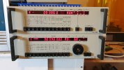
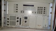
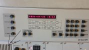
The control protocols differ between the CR90 and the TD90, as the front panels map
control information in different ways.
Also, it is likely that the baud rates for the serial data links are different.
Most ARTRAC-modified CR90 uses 1600 Baud signalling with 8 data bits, 1 stop bit and odd parity in order to handle fast scanning requirements, but the TD90 used in the transmitter used the original 200 Baud.
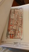
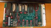
The pin-outs for the remote control board in the CR90 are identical, the control link is an opto-isolated V.28 interface, and the back-signalling link uses either V.28 or open-collector TTL levels.
Back-signalling, which is identical to the data used for updating the front panel,
is done as with a format where the data address uses the MSB nibble and the actual data
is contained in the LSB nibble.
From memory, the data map used in the CR90 looks like this:
MSB LSB
0 channel number LSD (0-9)
1 channel number MSD (0-9)
2 1 Hz digit (0-9)
3 10 Hz digit (0-9)
4 100 Hz digit (0-9)
5 1 kHz digit (0-9)
6 10 kHz digit (0-9)
7 100 kHz digit (0-9)
8 1 MHz digit (0-9)
9 10 MHz digit (0-2)
A Test meter value (0-F)
B Device address (usually F)
C Bandwidth/50 ohms/Hi-Z (0-9)
D MGC/AGC (0-9)
E Mode/20 dB attenuator (0-9)
F Test meter function (0-9)
TD90:
MSB LSB
0 channel number LSD (0-9)
1 channel number MSD (0-9)
2 100 Hz digit (0-9)
3 1 kHz digit (0-9)
4 10 kHz digit (0-9)
5 100 kHz digit (0-9)
6 1 MHz digit (0-9)
7 10 MHz digit (0-2)
8 Last used function (0-9)
9 Test meter value (0-F)
A Device address (usually F)
B Mapping of status LEDs (0-F)
C Test meter function (1-7)
D Mapping of Hi/Lo power and PA off/on LEDs (0-9)
E Mapping of Simplex/Duplex and MOX on/off LEDs (0-9)
F Mode (1-F)
Pin-out for the remote control board 25-pin connector X2:
1 common for V.28 (strap to ground)
2 TTL remote control message, strap to 4
3 serial status output TTL
4 TTL remote control input
9 ground
11 serial status output V.28
Hope this helps.

